

Project Description
Normally we see drones controlled using an RF remote, or for autopilot using a GPS module to control it automatic by giving proper direction by it. But in my project, I have gone about things in another way using an Arduino Uno. The main objective of this project is to collect data and 2D video information from a particular known area. In order to get the information, we must to assign the values of length and width that the drone can travel using Arduino programming. As its name suggests, autopilot means that the drone will be handled by itself, while controlling action of the drone will be handled by a flight controller that has built-in sensors to balance the drone. An Arduino Uno is the brain of the system, which gives the proper signal to flight controller. To maintain stability and sustained operation, I used an OpenPilot CC3D microcontroller (or any flight controller), along with a camera to capture live data with weather monitoring sensors. Finally, the system includes a Bluetooth module to turn the dronon/off and display the live data using a Android mobile device.
Step 1: ARDUINO UNO and PWM
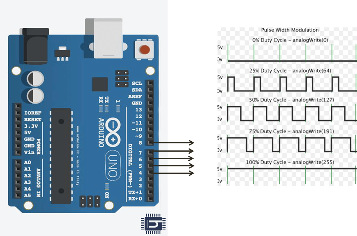
as we know the arduino Uno is a Atmega Micro controller. here i generated PWM signals to control the Drone.
Feel free to use different colors for the eyes or even hand-paint them after printing. The universal joints play a critical role in the smooth motion of the eyes, allowing them to mimic realistic movements.
Step 2: CC3D flight Controller

as we seen in above fig shows the a flight controller which having inbuilt gyro and accelerator controller and auto leveling features. But these micro controllers company provides its own software to program it, and its is user friendly to use. these micro controller needs a PWM signals for input to control the individual BLDC motors. these signals will be generated by arduino uno.
.
.
.